DIY 0-10V Input Switch Box (5 Switches)

Users Who Are Viewing This Thread (Total: 2, Members: 1, Guests: 1)

JeffB418

HYDROS Expert
Joined
Jun 25, 2020
Messages
1,143
Reaction score
330
Location
Syracuse NY
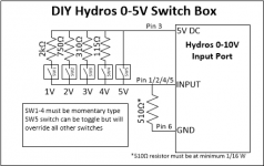
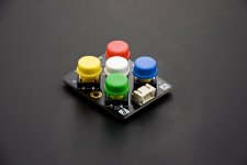
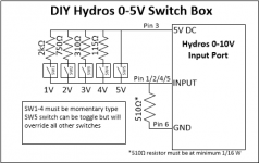
Here is a simple way to use one of your 0-10V inputs and have 5 discrete switch inputs for 1V/2V/3V/4V/5V levels. This leverages the onboard 5V DC pin and uses a resistor ladder to create multiple voltages. Note that only 1 switch can be active at a time so momentary switches are recommended. Also the 5V switch will act as an override to all other switches. Using standard radial resistors make easy work of this circuit. If you want less switches, just leave out the associated resistor and switch from the diagram. Amazon has many industrial switch boxes with up to 4 switches as well, here is one Example.
1604932295783.png
 
Here is a simple way to use one of your 0-10V inputs and have 5 discrete switch inputs for 1V/2V/3V/4V/5V levels. This leverages the onboard 5V DC pin and uses a resistor ladder to create multiple voltages. Note that only 1 switch can be active at a time so momentary switches are recommended. Also the 5V switch will act as an override to all other switches. Using standard radial resistors make easy work of this circuit. If you want less switches, just leave out the associated resistor and switch from the diagram. Amazon has many industrial switch boxes with up to 4 switches as well, here is one Example.

View attachment 348
Thanks for sharing!
 
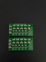
Someone needs to produce a little PCB for this. Just plug your two switch wires in here. Better yet in a little box to mount.
 
Someone needs to produce a little PCB for this. Just plug your two switch wires in here. Better yet in a little box to mount.
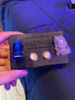
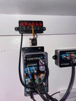
I've been assembling breakouts and switch boxes as fast as I can, but really need preassembled GX12-6 plugs. I have like 2 dozen of each model partially assembled, but am waiting for cables!

The switch boxes can be designed to plug directly into the 0-10v input, but that wastes the three other channels. So better option is my breakout + switch box.

I can send you a PCB if you need

IMG_8371.jpgIMG_8283.jpgIMG_8243.jpg
 
I've been assembling breakouts and switch boxes as fast as I can, but really need preassembled GX12-6 plugs. I have like 2 dozen of each model partially assembled, but am waiting for cables!

The switch boxes can be designed to plug directly into the 0-10v input, but that wastes the three other channels. So better option is my breakout + switch box.

I can send you a PCB if you need

View attachment 390View attachment 391View attachment 392


If you offer offer it as a full set up like with the switches above I would be interested.

My soldering days are over. I still have two irons and used to fix some pcb's for Classic arcade games but now that I am older harder to see and not as steady.

I am no electronics genius at all. For classic arcade games I could figure out dc power supplies or figure out if a trace was broken or reflow cold solder joints. nothing like what you two do.


I am very impressed with your work.

Jeff the stuff you have been doing is great too... I am sure it is greatly appreciated.

I myself have many hats and know a little about allot of things but not allot about one thing.

I took some electronics classes but basic stuff when I used to fix classic arcade games (coin op), I also work for a consulting Electrical engineer firm.
We basically engineer plans a electrician would follow and lighting. We do lots of lighting and lighting studies. I also do IT for them but we are a small company. I also installed DSL for a while so I know some IT. Funny thing is my degree is in mechanical Engineering which I have done almost none off.
 
Last edited:
I need one of these in my setup. If you sell them let me know.
 
If you offer offer it as a full set up like with the switches above I would be interested.

My soldering days are over. I still have two irons and used to fix some pcb's for Classic arcade games but now that I am older harder to see and not as steady.

I am no electronics genius at all. For classic arcade games I could figure out dc power supplies or figure out if a trace was broken or reflow cold solder joints. nothing like what you two do.


I am very impressed with your work.

Jeff the stuff you have been doing is great too... I am sure it is greatly appreciated.

I myself have many hats and know a little about allot of things but not allot about one thing.

I took some electronics classes but basic stuff when I used to fix classic arcade games (coin op), I also work for a consulting Electrical engineer firm.
We basically engineer plans a electrician would follow and lighting. We do lots of lighting and lighting studies. I also do IT for them but we are a small company. I also installed DSL for a while so I know some IT. Funny thing is my degree is in mechanical Engineering which I have done almost none off.

I need one of these in my setup. If you sell them let me know.

I cant seem to send messages on this forum, shoot me an email at Harrysaquatics@gmail.com. The options would be either a switch box that plugs directly into the 0-10v port, or the breakout box PLUS a switch box that has bare wire ends.

The benefit of direct connection is that it looks cleaner, is easier, and is more water resistant. But the drawback is you wont have access to the other 3 channels.
 
What is the input voltage resolution? Are we limited to 1v steps?
 
What is the input voltage resolution? Are we limited to 1v steps?
Yes, 1v steps on each of the 4 channels.

In reality the port is super accurate (can be used with analog sensors), but I guess they decided that 10 steps is sufficient on one channel. I agree with them, it keeps it nice and simple.

Its worth noting that only one voltage can be applied at a time, so having more and more resolution on a single channel doesn't give much returns. (Ex. if a float switch is closed providing 1v, no other switch can be closed on that channel or it will read an imperfect average of both ).
Thanks! That makes sense if it can be used as an analog input. Would you happen to know the voltage tolerance needed? If I have one switch as 3 volts, can I use 2.9-3.1?

Yeah, I agree, 10 steps is probably more than enough. Certainly is for me.

I'm just thinking "out loud" so I haven't done the maths yet, but in my setup, I have 3 float switches in the sump: a "sump high" alarm, an ATO switch, and a "sump low" alarm, in that order from top to bottom. There's only one water level, so the floats should always be switched sequentially depending on water level. I'm trying to see if it's possible to use one channel for all three. Is there a way to wire it like a series/parallel voltage divider? So that the bottom float is, say, 4 volts, the bottom AND the middle is 2 volts, and all three are 1 volt?

It rounds to the whole number , so you could just set that value (both dots) to 3.

IMO, all float switches or similar devices should go in between ground and a channel input. Therefor they will read 0 when triggered, as opposed to the floating value.

That is the simplest way to do it, and why my Hydros Breakout Box offers a ground under each channel input.

You can use a voltage divider circuit **only** if there is only the possibility of one switch closing at a time. I suppose you can do that with float switches by having opposite float switch orientations, where the lower one is closed when dry and the upper one is closed when wet. That way it should be impossible for both to be closed at the same time.

I think the voltage divider circuit is better for stuff like buttons or toggles- where you know only one will be triggered at a time.
 
CE8B6A83-862C-4C9A-AF7F-65752B5B4420.jpeg
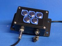
I now also make a prebuilt solution for those looking for a 5 button box. The secondary port on the box also allows you to connect addition boxes or Harry’s breakout to it so you can take advantage of the other 3 unused channels. The box is made out of the same style of IP67 boxes that hydros is so it will fit right in.

link to my products: https://www.jbaquaticsllc.com/s/shop

A full tutorial on how to use it:
 
tagging in aswell @jeffB14B loving the box ty. can you use 2 at once, or more? (boxes) i have a total of 1500 gallon home system and need a lot task to be done when doing maintenance. if this works out this will make it easy for my wife and friends to help me on my system when am on the road.
 
How bad of an idea would it be to use this for float switches. For example, say I have a high level float switch and a low level float switch in my RO/DI storage tank for an auto RO/DI set up. When the level is at the high limit, the high level switch is telling the Hydros that the tank is full and it shuts off the solenoids and booster pump. When the tank is empty, the low level switch is activated and the Hydros opens the solenoids and turns on the booster pump.
 
How bad of an idea would it be to use this for float switches. For example, say I have a high level float switch and a low level float switch in my RO/DI storage tank for an auto RO/DI set up. When the level is at the high limit, the high level switch is telling the Hydros that the tank is full and it shuts off the solenoids and booster pump. When the tank is empty, the low level switch is activated and the Hydros opens the solenoids and turns on the booster pump.
if you can guarantee that only 1 switch is closed at a time, this will work. But if there is any condition where both switches are closed at the same time, the resulting voltage will be wrong. You will have to configure the top float switch to be closed when submerged, and open when not. Then the lower switch you will need to configure the opposite as open when submerged and closed when not. This way when the water level is between the 2 float switches, neither switch is closed and only one or the other switches is closed based on if the water is over the high switch or below the low switch. You can normally reconfigure float switches by removing the clip and flipping the magnet around. Or just mount one inverted to the other one.

You could add another float as an override as well, switch 5 above in my circuit will always output 5V regardless of what SW1-4 are doing. So you could put this float at the very top of your RODI as a backup incase the top float switch failed for some case.

1631218161829.png

In summary:
Wire a lower float switch to SW1 in the above circuit, with the CLOSED state when it is not submerged.
Wire a upper float switch to SW3 (gives more error margin using 3 over 2) in the above circuit, with the CLOSED state when it is submerged.
Wire an optional overfill safety float switch to SW5 in the above circuit, with the CLOSED state when its submerged.
 
if you can guarantee that only 1 switch is closed at a time, this will work. But if there is any condition where both switches are closed at the same time, the resulting voltage will be wrong. You will have to configure the top float switch to be closed when submerged, and open when not. Then the lower switch you will need to configure the opposite as open when submerged and closed when not. This way when the water level is between the 2 float switches, neither switch is closed and only one or the other switches is closed based on if the water is over the high switch or below the low switch. You can normally reconfigure float switches by removing the clip and flipping the magnet around. Or just mount one inverted to the other one.

You could add another float as an override as well, switch 5 above in my circuit will always output 5V regardless of what SW1-4 are doing. So you could put this float at the very top of your RODI as a backup incase the top float switch failed for some case.

View attachment 1400

In summary:
Wire a lower float switch to SW1 in the above circuit, with the CLOSED state when it is not submerged.
Wire a upper float switch to SW3 (gives more error margin using 3 over 2) in the above circuit, with the CLOSED state when it is submerged.
Wire an optional overfill safety float switch to SW5 in the above circuit, with the CLOSED state when its submerged.
2 layers of redundancy to the Hydros sounds like a good idea to me. I already have a float valve in the tank so I'd essentially have 3 levels of redundancy. I also have a saltwater mixing container I plan to wire a low level switch to to stop the circulation pump if the level drops to low. This would obviously be on a different channel, and I'd likely wire up a push button as well to manually run the pump should I need to pump some saltwater out. So in this scenario, I'd wire the push button to SW1, 1 float switch to SW3, and one to SW5. Then program Hydros to shut off the pump if it detects 3V, 4V, or 5V. This way if I manually run the pump and accidentally run the water level too low, SW3 closes, if SW1 is still closed, it adds up to 4V triggering Hydros to kill the pump. And SW5 for redundancy. In theory, I could do the RO/DI floats on channel 1, the salt mixing station on channel 2, and still have two open channels, right?
I can send you a PCB if you need
If you have any PCBs left, would you be willing to send me 2, and how much are you charging for them?
 
@TheHarold I just purchased the switchbox from you. I am looking for a way to potentially trigger a sudo low power mode when the power goes out without using an Icecap battery pack. I was thinking about feeding your switchbox with external 5v DC power from a USB brick plugged into the wall. This 5v constant will be a new 'Normal' mode and switches would still modify that 5v for other modes. In the event the power is lost, 0v would be the input for the lower power mode. Thoughts??
 
Back
Top