
JeffB418
HYDROS Expert
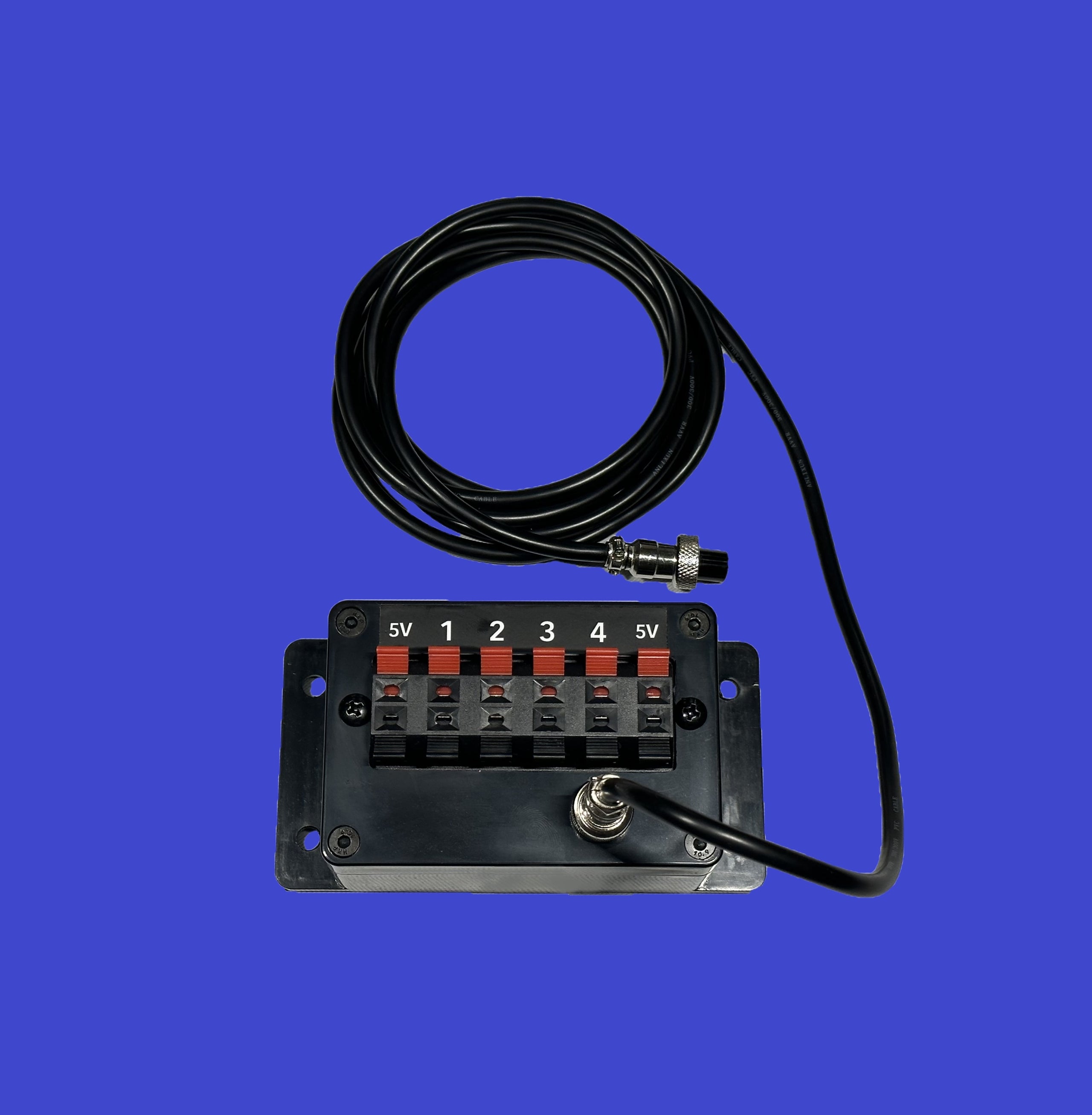
I've added a break out box to the line of JBA products.
 www.jbaquaticsllc.com
This new product allows easy access to the 0-10V port channels for DIY projects. Each 0-10V GX12-6 connector on the Wave Engine, Wave Engine Light Ed, and Control X4 actually has 4 input or output channels each. Connecting this box to your 0-10V INPUT port gives you access to the 4 channels plus the 5V output supply. This allows you to connect up discrete buttons or switches to your Hydros such as magnetic door reed switches, magnetic float switches, push buttons, and more. Any input that provides a open and closed state between 2 wires. Just connect the switch between the red input for that channel and the black ground. Hydros will sense 2.5V on an open/floating switch input, and 0V/GND when the switch is closed/engaged. Additionally you can use Single Pole Double Throw (SPDT) switches with the common leg connected to the input port, and the 2 pole ports connected to 5V and Ground each to be able to have a 3 state input (High/5V, floating 2.5V, and Low/0V).
This BoB also allows users to interface analog signals to the Hydros such as this Room and Humidity sensor: DFR0588 DFRobot | Development Boards, Kits, Programmers | DigiKey
Since this board draws very low power, you can power it from the supplied 5V on the box, and then interface the analog humidity channel to one BoB input channel, and room temp to another input channel. Do note that you can only draw up to 150mA MAX on the 5V output, and this is shared between both input and output 0-10V ports if the device has both.
Finally you can also use this box on the 0-10V OUTPUT port as well to interface to other 3rd party devices for control if the standard 0-10V cables can't be used. There is also a secondary GX12-6 port on the front of the box that is identical to the pinout on the Hydros, allowing users to passthrough any signals needed. In the case of 0-10V outputs, you can use a standard hydros adapter cable (the 3.5mm cable for example) to interface to 2 pumps via this secondary port, and then use the break out box terminals to adapt the other 2 channels to a different interface connector.
The secondary connector on the front can also be used to interface to existing JBA accessories such as the JBA Button Box when used on the 0-10V Input port, just note that what ever channel the secondary accessory is using (Channel 1 in the case of the JBA Button Box), cant be used on the breakout box since its already being used. But that does give you access to the other 3 unused channels.
The following devices have a 0-10V INPUT port:
Control X4
Wave Engine
Wave Engine LE
The following devices have a 0-10V OUTPUT port:
Control X4
Wave Engine
Follow the instructions here on how to add switches and sensors to your Hydros via the app here: HYDROS Control - How to add a 0-10V Input

Interfacing to the DFR0588:

Connect the white header harness to either the port with RH (room humidity) or T (temp). Using wire cutters remove the black header and strip the wires. Connect the RED wire to the 5V port on the BoB, Black to any Black port on the BoB, and the Blue wire to 1 of the 4 inputs. If you want to run both temp and humidity, only connect the blue wire of the secondary harness, red and black wires can be removed on the secondary harness. In hydros, to add these inputs to your device, refer to the sections "Adding Room Temp Input" and "Adding Humidity Input" at the following tutorial: https://www.jbaquaticsllc.com/hydros-humiditytemp-module
If you ever want to debug an input to see what Hydros is reading for actual voltages, add a new input as follows:

This section goes over a way to display the actual voltage being driven to your Input port for diagnostic purposes. Note that you can have both this and other types of inputs existing at the same time on your Hydros dashboard.
To make a diagnostic input first make another new input of Type 0-10V Input. Then select Analog for the Input Mode. Select the input number you'd like to monitor. Leave the Scale Factor and Offset to the values displayed, and finally select Generic. This will now show you the actual voltage being read by hydros on that input. You can do this for multiple inputs to monitor whats being read.
Hydros 0-10V Port Breakout Box | JB Aquatics LLC
Available for order! Units can take up to 1 week to ship, units are built to order. Typically I try my best to turn orders ASAP.FREE SHIPPING in the lower 48 US States!Tutorial on how to use the Hydros Breakout Box here: https://www.jbaquaticsllc.com/hydros-breakout-box9/22/2022: Updated Design...
This new product allows easy access to the 0-10V port channels for DIY projects. Each 0-10V GX12-6 connector on the Wave Engine, Wave Engine Light Ed, and Control X4 actually has 4 input or output channels each. Connecting this box to your 0-10V INPUT port gives you access to the 4 channels plus the 5V output supply. This allows you to connect up discrete buttons or switches to your Hydros such as magnetic door reed switches, magnetic float switches, push buttons, and more. Any input that provides a open and closed state between 2 wires. Just connect the switch between the red input for that channel and the black ground. Hydros will sense 2.5V on an open/floating switch input, and 0V/GND when the switch is closed/engaged. Additionally you can use Single Pole Double Throw (SPDT) switches with the common leg connected to the input port, and the 2 pole ports connected to 5V and Ground each to be able to have a 3 state input (High/5V, floating 2.5V, and Low/0V).
This BoB also allows users to interface analog signals to the Hydros such as this Room and Humidity sensor: DFR0588 DFRobot | Development Boards, Kits, Programmers | DigiKey
Since this board draws very low power, you can power it from the supplied 5V on the box, and then interface the analog humidity channel to one BoB input channel, and room temp to another input channel. Do note that you can only draw up to 150mA MAX on the 5V output, and this is shared between both input and output 0-10V ports if the device has both.
Finally you can also use this box on the 0-10V OUTPUT port as well to interface to other 3rd party devices for control if the standard 0-10V cables can't be used. There is also a secondary GX12-6 port on the front of the box that is identical to the pinout on the Hydros, allowing users to passthrough any signals needed. In the case of 0-10V outputs, you can use a standard hydros adapter cable (the 3.5mm cable for example) to interface to 2 pumps via this secondary port, and then use the break out box terminals to adapt the other 2 channels to a different interface connector.
The secondary connector on the front can also be used to interface to existing JBA accessories such as the JBA Button Box when used on the 0-10V Input port, just note that what ever channel the secondary accessory is using (Channel 1 in the case of the JBA Button Box), cant be used on the breakout box since its already being used. But that does give you access to the other 3 unused channels.
The following devices have a 0-10V INPUT port:
Control X4
Wave Engine
Wave Engine LE
The following devices have a 0-10V OUTPUT port:
Control X4
Wave Engine
Follow the instructions here on how to add switches and sensors to your Hydros via the app here: HYDROS Control - How to add a 0-10V Input
Interfacing to the DFR0588:
Connect the white header harness to either the port with RH (room humidity) or T (temp). Using wire cutters remove the black header and strip the wires. Connect the RED wire to the 5V port on the BoB, Black to any Black port on the BoB, and the Blue wire to 1 of the 4 inputs. If you want to run both temp and humidity, only connect the blue wire of the secondary harness, red and black wires can be removed on the secondary harness. In hydros, to add these inputs to your device, refer to the sections "Adding Room Temp Input" and "Adding Humidity Input" at the following tutorial: https://www.jbaquaticsllc.com/hydros-humiditytemp-module
If you ever want to debug an input to see what Hydros is reading for actual voltages, add a new input as follows:
This section goes over a way to display the actual voltage being driven to your Input port for diagnostic purposes. Note that you can have both this and other types of inputs existing at the same time on your Hydros dashboard.
To make a diagnostic input first make another new input of Type 0-10V Input. Then select Analog for the Input Mode. Select the input number you'd like to monitor. Leave the Scale Factor and Offset to the values displayed, and finally select Generic. This will now show you the actual voltage being read by hydros on that input. You can do this for multiple inputs to monitor whats being read.
