I have soldered a gx12 6 pin connector to 2 wires on a float switch. I can’t seem to get it to work. Float has been checked and has around 2.5v when closed. But when open it doesn’t change status. Almost like it’s getting constant voltage regardless.
Navigation
Install the app
How to install the app on iOS
Follow along with the video below to see how to install our site as a web app on your home screen.
Note: This feature may not be available in some browsers.
More options
You are using an out of date browser. It may not display this or other websites correctly.
You should upgrade or use an alternative browser.
You should upgrade or use an alternative browser.
0-10v Float switch
- Thread starter BigAsh
- Start date
- Tagged users None
Users Who Are Viewing This Thread (Total: 0, Members: 0, Guests: 0)
Danny
HYDROS Expert
What pins are you connecting it to?
Pins 3 and 1What pins are you connecting it to?
Pins 3 and
Pins 3 and
Also appear to only see 2.5v, shouldn’t I see 5v?What pins are you connecting it to?
- Admin
- #7
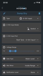
Use the 0-10V Diagnostics Input to determine the voltage when wet and dry. Then change the range so that the lower number is OUTSIDE the range.
Danny
HYDROS Expert
I have never used pin 3. I go from the input pin to ground or pin 6 with the switch, If fact for float switches i connect them to the sense port. Those 6 pin on GX connectors very close to each other. I usually get the quad cable and then connect with a 3.5 mm jack instead of trying to create my own cable.
I did originally connect to the sense and it worked fine, but I needed one more port and figured try it on the 0-10, so based on what your saying you wouldn’t need the 5v supply? My understanding is pin 3 is 5v then the pin one would be the input, so I am assuming and may have this wrong but I would think when the switch is closed pin one would sense 5v and when open 0. Didn’t think it needed ground.I have never used pin 3. I go from the input pin to ground or pin 6 with the switch, If fact for float switches i connect them to the sense port. Those 6 pin on GX connectors very close to each other. I usually get the quad cable and then connect with a 3.5 mm jack instead of trying to create my own cable.
Thank you, I have done this and my voltage does not change in open or closed. When I pin out my connector it does show the switch is operating correctly but I don’t see a voltage drop when connected.Use the 0-10V Diagnostics Input to determine the voltage when wet and dry. Then change the range so that the lower number is OUTSIDE the range.
Danny
HYDROS Expert
The inputs float open at around 2.5v. They do not go to 0 unless you add a switch from the pin to ground. You can setup the input to measure the voltage. Carlos posted a link on how to do this for you. If do that then you can see what the input is doing when you open and close the switch.
Thank you I will try thisThe inputs float open at around 2.5v. They do not go to 0 unless you add a switch from the pin to ground. You can setup the input to measure the voltage. Carlos posted a link on how to do this for you. If do that then you can see what the input is doing when you open and close the switch.
Thank you for this info, everything is working nowThe inputs float open at around 2.5v. They do not go to 0 unless you add a switch from the pin to ground. You can setup the input to measure the voltage. Carlos posted a link on how to do this for you. If do that then you can see what the input is doing when you open and close the switch.