Interfacing Gredia flow sensors to the Hydros

Users Who Are Viewing This Thread (Total: 1, Members: 0, Guests: 1)

ggdowski

Member
Joined
Oct 20, 2021
Messages
48
Reaction score
29
Location
Rochester
Screen Shot 2022-03-27 at 12.36.30 PM.png
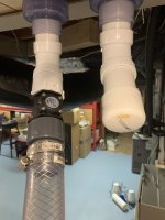
I have been asked several times about how to interface the Gredia flow sensors that can be purchased on Amazon (located here). I have had 3 of these sensors in operation on the Hydros for about 2 months. I have a 1.5" model on my return pump and I have 2 of the 0.5" models on my reactors. These flow sensors are paddle sensors. They are similar in concept to the ones that are used on the Apex. The paddles are inline with the flow of water within the pipe. The rate at which the paddles spin is used as a measure of flow rate within the pipe. They generate a digital signal that is a pulse pattern when the paddles are spun. The flow rate is computed by dividing the number of pulses counted by the time over which they occurred. These sensors have a few drawbacks because the paddles are within the flow of water that should be mentioned.
  1. They impede flow of water to some degree. Thus, they will slightly reduce your overall flow rate because it is more difficult for the pump to push the water through the pipe. While this is certainly an issue, the head loss due to several 90degree turns will be far more significant than the increase in impedance due to incorporating a flow sensor.
  2. They are susceptible to having stuff grow on them or get caught on them. I try to use these on the "clean" side of my system after the water has gone through a filtration stage. Later in this thread, I'll show you what I observed in the first 2 months of operation with the 1.5" model.
I think these drawbacks are some of the primary reasons that people would prefer to buy a sensor that is not within the stream of water. Such sensors do exist, however, they are currently about 5-6x more expensive. The Gredia sensors currently range in price from $8-25/sensor. If you use these sensors, I suggest that you place them in your system where you can easily take them out for inspection and cleaning. Every system is unique, but I expect to pull these out 1-2x/year.
 
IMG_8420.jpgOk, so how do you interface these to the Hydros?
The first thing to keep in mind is that these absolutely must be connected to a Sense input on the Hydros. There is a setting for a flow rate sensor on the 0-10V input lines -- however, that input assumes that your sensor is an analog sensor. The Gredia flow rate sensors (and the Apex sensors) are digital sensors and they will not function properly with the 0-10V input lines on the hydros (at least at the time of this post). So you must have an available Sense input on your Hydros if you wish to use these.

The Sense input of the Hydros utilizes a 4pin GX12 connector. You will notice that the cable on the Gredia only has 3 wires (not 4). The wire definitions are on the front of the Gredia device. The following list defines how they are connected to the GX12 4pin connector:
  1. pin 1 -- yellow -- Signal output to be connected to pin 3 on the Hydros 4pin GX12 connector
  2. pin 2 -- black -- Ground to be connected to pin 1 on the Hydros 4pin GX12 connector
  3. pin 3 -- red -- +5V to be connected to pin 2 on the Hydros 4 pin GX12 connector
There are a number of strategies that can be utilized to make this connection.
  1. open up the device, remove the 3 wires, buy a prefabricated GX12 4pin wire, cut off a connector, and solder the wires directly to the device.
  2. cut off the connector on the Gredia, buy a prefabricated GX12 4pin wire, cut off a connector, and splice the wires together.
  3. cut off the connector on the Gredia, buy a set of mated GX12 connectors, solder the male mate to the Gredia. Buy a prefabricated GX12 4pin wire, and connect that to the Hydros.
I have done all three. #1 is somewhat difficult but feasible. #2 is easier but can look klugy if you are not good at splicing wires together. #3 is the best option because it is a cleaner connection. It is also easier to manage because you can disconnect it in close proximity to the pipe.
The picture shown is what the end result looks like.
 
Let's get into the nitty gritty on this post.

IMG_8410.jpg
  1. The first thing you will have to do is to cut off the connector on the Gredia flow sensor and prepare it to solder on a GX12 connector.
  2. I removed the white cover over the wires and replaced it with heat shrink tubing. That is optional.
  3. I placed the body of the connector over the wires. See orientation in the picture -- that is important. You will also have to remove the strain reliever on the body of the connector (two small screws).
  4. Trim the wires to about 3mm so that they are all the same length. Expose about 1mm of each wire. Lightly tin each wire by applying a small amount of solder to each wire. The lengths are important in this step because if they are too long then the heat shrink will pop out of the back of the connector when it is fully assembled.


IMG_8403.jpg
Now you are going to solder the connector to the wires. The connector component will have a flat edge. If you rotate the connector so that the flat edge is on the left, pin 1 will be located on the top left. You will also be able to see that each pin is labeled (1-4) -- but it can be hard to see.


IMG_8412.jpg
The picture at the right shows the first wire that was soldered.
Again.

Black -- goes to pin 1
Red --- goes to pin 2
Yellow --- goes to pin 3


IMG_8413.jpg

When you are done soldering all three wires it will look like this:


IMG_8414.jpg


IMG_8415.jpgThe final step is to slide the connector base and screw it to the soldered wires side. You will also have to reconnect the strain relief. This connector will now allow you to connect the sensor to a hydros sense input with a simple GX12 4pin female to female wire. You can buy those on amazon as well.
 
IMG_8421.jpgNow it is time to hook it up. Here is what mine looks like. This is the return from my basement sump. I built two returns, but I am currently only using one. You can see the Gredia sensor installed on the left return.


I have that connected to the hydros with this setup.Screen Shot 2022-03-27 at 2.29.21 PM.png

Notice that it is defined as a Sense Port, that is designated as a Flow Rate Sensor. I have selected the model that corresponds to the pipe size for this unit (FM-150).

Here is what I can report (note -- I only have access to the same amount of data that you have access to - 5days). So if you want to know about the stability over two months -- you are asking me for something I don't have.

Screen Shot 2022-03-27 at 2.28.57 PM.png

You might be wondering why there is a dropout. That is when I took it offline today to inspect it. You can see what it was reporting before and after I cleaned it. The left picture is when I took it off and inspected it. It is a little dirty after two months -- but not bad. I cleaned it (right picture) and put it back into service. No change in reported rates. Granted that is only after 2 months.... I'll report back in another 6 months.
IMG_8394.jpgIMG_8395.jpg

You might be wondering what is around the perimeter in those pictures above. These are food grade sensors. The 1.5" model has a small metal ring on the inside that is in contact with the water. I wasn't comfortable with that -- so I put some silicone over it using a q-tip. Interestingly, the 0.5" models do not have that metal ring on the inside. One concern I had was whether it would rust. It hasn't in the two months that I have been using it. I'll keep watching it.
 

Attachments

  • IMG_8421.jpg
    IMG_8421.jpg
    2.1 MB · Views: 5
I thought I would post one more picture to help illustrate the utility of the flow rate sensor. I can imagine that the figure of my display tank flow rate is not that impressive as it was constant for 5 days without any change at all. So you might be saying -- why bother?

The other two that I have, I use on a carbon and GFO reactor. As we all know using GFO is tricky. However, using flow rates can help. It can tell you what the starting rate was and how it is performing over time. I was very surprised to see just how fast my carbon and GFO reactors slowed down over time.
Here is a plot of my GFO reactor over the last five days.
Screen Shot 2022-03-27 at 9.18.11 PM.png

I have seen this effect pretty routinely --- where the rate decreases steadily to almost zero over 5-10days. At first I thought it was the flow rate sensor. However, sure enough, when I went and checked it today it was barely flowing. I was able to get it reflowing by adjusting my ball valves. However, I know that it will continue to do this until it can't be "reset".

Even if you do not like using GFO, this technique is good for measuring the flow rate through your Carbon reactor (and knowing when it has stopped functioning). I am also using it to measure the flow rate through my refugium -- with the eventual goal of controlling the rate to optimize the levels of nitrates in my tank. That would be cool if I could get that to work.
 
Any idea by how much these reduce flow? Hopefully not anything big since it mostly just have to spin a small prop, but still :)
 
I don't really know exactly. Except that I can blow on them and generate a signal that is 850G/hr. It doesn't take much to spin them. I just don't know how much friction or impedance they impart in fluid.
 
Thanks for the response! I wouldn't think it would block too much and I guess I could go with 2" version to reduce any restrictions from measurement chamber size.

One more question :) I see few people complain about thread sizing on these, looks like you have them on standard pvc, any issues with that?
 
Back
Top