JeffB418
HYDROS Expert
This tutorial will go over how to install a termination resistor in your hydros power supply connector so you do not need a dongle version. This is handy in cases where you have a data only cable between two hydros devices in a collective.
what you need:
- 24v hydros power supply
- 1/4watt 120 ohm leaded resistor
- electrical tape or shrink tubing
- soldering iron and skills
first remove the 2 screws a the collar. Then spin the housing from the connector head and slide back down the wire to expose the gx12-5 pins
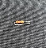
cut your 120 ohm resistor as follows

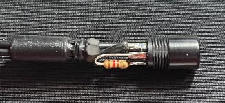
then solder the resistor between connector pins 2/3. Pins are labeled on the face of the black connector for reference

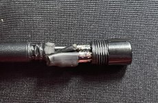
Either wrap the exposed resistor with a small piece of electrical tape or heat shrink to prevent contact with metal connector housing

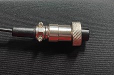
reinstall housing and screws

test resistance between connector pins 2/3 with an ohm meter. Then plug it in and measure 24vdc across pins 1/5. Then your good to go!
what you need:
- 24v hydros power supply
- 1/4watt 120 ohm leaded resistor
- electrical tape or shrink tubing
- soldering iron and skills
first remove the 2 screws a the collar. Then spin the housing from the connector head and slide back down the wire to expose the gx12-5 pins
cut your 120 ohm resistor as follows

then solder the resistor between connector pins 2/3. Pins are labeled on the face of the black connector for reference

Either wrap the exposed resistor with a small piece of electrical tape or heat shrink to prevent contact with metal connector housing

reinstall housing and screws

test resistance between connector pins 2/3 with an ohm meter. Then plug it in and measure 24vdc across pins 1/5. Then your good to go!
